
Solar Module Mounting Structure (MMS): Components, Materials & Manufacturing Process Explained
 Practical Notes
Solar modules and inverters usually receive most of the attention in a solar project, but the steel framework supporting the modules performs an equally important function. A Solar Module Mounting Structure (MMS) holds photovoltaic modules in the required position and provides the structural framework through which loads are transferred to the supporting system.
For solar EPC companies, developers, structural consultants and procurement teams, selecting an MMS is therefore not simply a matter of comparing steel prices. The section profile, steel thickness, material specification, coating requirement, hole pattern, fabrication accuracy and project drawings can all affect manufacturing as well as installation at site.
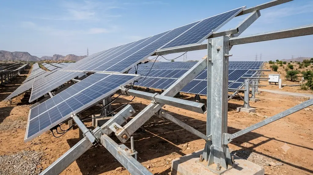
A ground-mounted solar structure may include columns, rafters, purlins, bracing members, connection components and fasteners. The exact configuration varies from one project to another and should follow the approved structural design.
This guide explains the main components of a solar module mounting structure, commonly used materials, how different profiles fit into an MMS and the typical manufacturing process followed before the structure is dispatched for installation.
What Is a Solar Module Mounting Structure?
A Solar Module Mounting Structure is the structural framework used to support and position solar PV modules. It provides the connection between the modules and the supporting foundation, pile or roof system, depending on the type of installation.
In a ground-mounted solar project, the MMS generally consists of several interconnected steel members rather than one single component. Columns or posts provide primary support, rafters form the main frame, purlins support the module rows and bracing helps stabilize the overall structure.
The dimensions and configuration of these members are determined by engineering requirements. Factors such as module arrangement, structural loads, project layout, connection design and site conditions can influence the final section selection.
This is why an MMS should be treated as an engineered structural system, not simply as a collection of standard steel profiles.
Main Components of a Solar Module Mounting Structure
The terminology used in fabrication and structural drawings can vary between projects, but the following members are commonly found in ground-mounted solar mounting structures.
1. Columns or Posts
Columns form the primary vertical support of the structure. They transfer loads from the upper members towards the pile, foundation or other supporting system specified for the project.
The column profile, dimensions, thickness, length and connection details should correspond with the approved structural drawings. Depending on the design, different cold-formed or structural steel sections may be used.
2. Rafters
Rafters form an important part of the main structural frame. They are generally connected to the supporting columns and provide the framework on which the purlins or module-supporting members are positioned.
Rafter dimensions and hole locations need to match the project drawings accurately because incorrect spacing can affect the alignment of other MMS components during installation.
3. Purlins
Purlins are positioned closer to the solar modules and provide supporting lines for module installation. Depending on the engineering design, an MMS may use C purlins, HAT purlins, Z sections or other cold-formed profiles.
Shree Deepak Industries manufactures galvanized C and Z purlins in multiple specifications for structural applications. For a solar MMS project, however, the final section size, thickness and profile should always follow the approved engineering requirement.
4. Bracing Members
Bracing members help stabilize the structural frame by connecting different parts of the MMS. Their configuration can vary depending on the project design.
Rather than assuming a standard bracing arrangement, manufacturers should follow the profile, length, hole pattern and connection details given in the fabrication drawings.
5. Connection Plates and Supporting Components
Solar mounting structures can also include brackets, connection plates, splice members, clamps and other supporting components.
These parts may be smaller than the primary structural members, but dimensional accuracy remains important. Incorrect hole spacing or connection geometry can create alignment issues when the structure is assembled at site.
6. Fasteners
Bolts, nuts, washers and other fastening systems connect structural members and module-supporting components according to the approved assembly design.
The fastener grade, diameter, coating and installation requirement should be specified by the project engineer or procurement specification rather than assumed by the fabricator.
Which Materials Are Used for Solar MMS?
There is no single steel specification or coating system that is suitable for every solar project.
The appropriate material depends on the structural design, environmental conditions, required service performance and project specifications. Solar module mounting structures may use galvanized steel, aluminium-zinc coated steel or other approved coated steel systems depending on the engineering requirement.
Galvanized Steel
Galvanized steel is widely used for outdoor structural applications because the zinc coating provides a protective layer over the base steel.
The required steel grade, coating method and coating specification should be clearly defined in the project documents. Different coating requirements should not be treated as interchangeable simply because the finished profiles look similar.
Galvalume or Aluminium-Zinc Coated Steel
Some solar structure designs may specify aluminium-zinc coated steel for selected members. The exact material grade, steel thickness and coating requirement should again be selected according to the approved engineering specification.
Shree Deepak Industries also lists galvanized, Galvalume and coated steel coils across its steel product range.
Why Material Specification Matters
Before production begins, the manufacturer and buyer should have clarity on:
- Steel grade
- Material thickness
- Required coating
- Coating specification where applicable
- Section dimensions
- Applicable material documentation
If the project requires mill certificates, coating documentation, inspection records or specific traceability requirements, these should preferably be communicated before manufacturing starts.
C Purlin vs HAT Purlin in Solar Module Mounting Structures
C and HAT profiles can both be used within solar mounting structures depending on the engineering design, but they should not automatically be considered substitutes for each other.
| Factor | C Purlin | HAT Purlin |
| Profile shape | Open C-shaped cold-formed section | Top-hat shaped cold-formed section |
| Possible solar use | Can be specified for purlins or other supporting members depending on the design | Can be specified as a module-supporting purlin depending on the design |
| Dimensions | Determined by structural requirement | Determined by structural requirement |
| Material and thickness | As specified in project drawings | As specified in project drawings |
| Selection basis | Structural design, loading and connection requirement | Structural design, loading and connection requirement |
The more useful question for an EPC or procurement team is therefore not whether a C purlin or HAT purlin is universally better. The correct profile is the one that has been engineered for the particular module mounting structure.
Solar MMS Structure Manufacturing Process
Solar MMS structure manufacturing normally begins well before the material reaches the forming line. Project drawings, section dimensions, material specifications, tolerances and quantities first need to be translated into a controlled manufacturing requirement.
The exact production process depends on the profile and material specification, but the following stages explain a typical workflow for cold-formed solar structural members.
Step 1: Review the Approved Drawings and Specifications
The first step is understanding exactly what needs to be manufactured.
The production team may need to review:
- Section profile and dimensions
- Material grade
- Steel thickness
- Member length
- Hole diameter
- Hole spacing and punching pattern
- Coating or finish requirement
- Quantity
- Part identification
- Applicable dimensional tolerances
This becomes particularly important on utility-scale projects where several visually similar members may have different dimensions or hole patterns.
Step 2: Raw Material Selection
Steel coils or other input materials are selected according to the project specification.
The material grade, thickness, coating and width should correspond with the approved production requirement. Where multiple projects or profiles are being manufactured simultaneously, proper material identification also becomes important.
Step 3: Coil Slitting
Cold-formed sections are often manufactured from steel coil. Before forming, a wider coil may need to be cut into narrower strips of the required width. This process is known as coil slitting.
The slit width is determined by the developed width of the final profile. Consistent slitting helps the material feed correctly during profile forming.
Shree Deepak Industries lists GP, Zincalume and colour-coated slit coils for solar structures, cable trays, construction and other industrial applications.
Step 4: Roll Forming
During roll forming, the prepared strip passes through a sequence of forming rollers that gradually shape the steel into the required profile.
This process is commonly used to manufacture cold-formed sections such as C, Z and HAT-type profiles.
Tooling and machine setup need to correspond with the required profile dimensions so that the produced section remains consistent across the production batch.
Step 5: Punching and Hole Preparation
Solar MMS members usually require holes or slots for structural connections and installation.
Hole size, pitch and position should correspond accurately with the approved drawing. Even a relatively small dimensional error can become significant when the same connection is repeated across a large number of structural members.
Accurate punching therefore helps reduce alignment issues when components are assembled at the project site.
Step 6: Cutting to Length
The formed profiles are cut to the required member lengths shown in the project drawings or bill of materials.
Different structural components may use the same profile but require different lengths, so correct part identification is important throughout manufacturing.
Step 7: Surface Protection
The surface-protection stage depends on the material route specified for the project.
Some sections may be manufactured from already coated material, while other project specifications may require a different approved galvanizing or finishing route.
The manufacturer should follow the stated project specification rather than assuming that one coating system is suitable for every solar installation.
Step 8: Dimensional and Quality Checks
Before dispatch, the manufactured components should be checked against the agreed requirements.
Depending on the product and quality plan, inspection may include:
- Profile dimensions
- Material thickness
- Member length
- Hole size
- Hole pitch and position
- Straightness
- Visible deformation
- Surface condition
- Quantity
- Part identification
Any required inspection records or documentation should ideally be agreed between the buyer and manufacturer during the order stage.
Step 9: Bundling, Identification and Dispatch
Solar MMS projects can involve a large number of similar-looking components. Proper bundling and identification can therefore help the site team reconcile material more efficiently after delivery.
Packaging should protect the material during handling and transport while also making the different profiles and part numbers easier to identify.
What Information Should an EPC Include in a Solar MMS RFQ?
A quotation can only be as accurate as the information provided with the enquiry.
An enquiry that simply asks for a price for a “solar structure” leaves several important variables undefined. A more complete RFQ allows the manufacturer to understand the technical and commercial requirement before pricing.
Where available, an MMS enquiry should include:
- General arrangement drawings
- Fabrication drawings
- Bill of materials or member schedule
- Required section dimensions
- Material grade
- Steel thickness
- Coating specification
- Hole and punching requirements
- Quantity or project tonnage
- Inspection requirements
- Required documentation
- Packing requirements
- Delivery location
- Required project schedule
Providing this information early can reduce unnecessary clarification rounds and make it easier to compare quotations on an equivalent technical basis.
Common Mistakes When Procuring Solar Module Mounting Structures
Comparing Only the Price Per Kilogram
The lowest price per kilogram does not necessarily represent an equivalent quotation.
Material grade, coating specification, punching, tolerances, packing, documentation and scope of supply may differ between vendors. Technical scope should therefore be aligned before commercial comparisons are made.
Assuming Every C or HAT Section Is the Same
A profile name does not fully define a structural component.
Web width, flange dimensions, lip dimensions, steel thickness, material grade, length and hole pattern can differ from one MMS design to another.
Starting Production from an Unapproved Drawing
Manufacturing against a preliminary or outdated drawing can create avoidable rework if the structural design changes later.
The drawing revision released for production should therefore be clearly identified before manufacturing begins.
Ignoring Hole Pattern and Connection Details
A structurally suitable profile can still create installation problems if holes and slots do not align with the mating components.
Punching requirements deserve the same attention as the section dimensions.
Ignoring Packing and Part Identification
Large solar projects may involve thousands of individual structural members. Even when the components are manufactured correctly, poor identification can make material reconciliation at site more difficult.
Bundle identification and part marking requirements should therefore be discussed before dispatch.
How Shree Deepak Industries Supports Solar Structure Requirements
Shree Deepak Industries is based in Jaipur, Rajasthan, and its website presents capabilities around solar structure manufacturing, including C, Z and HAT profile requirements, custom profile design, precision roll forming, GI and coating protection, quality checks, packaging and dispatch planning.
The company’s existing product range also includes C and Z purlins, slit coils and steel coils that are relevant to different industrial and structural requirements.
For an actual Solar Module Mounting Structure requirement, the section profile, dimensions, steel grade, thickness, coating and manufacturing scope should be finalized according to the project’s approved drawings and specifications.
If you are planning a solar project, you can share your drawings, specifications, quantity and delivery requirement with Shree Deepak Industries for review and quotation.
Frequently Asked Questions About Solar Module Mounting Structures
What does MMS mean in a solar project?
MMS stands for Module Mounting Structure. It is the structural framework used to support and position solar photovoltaic modules and transfer structural loads towards the supporting foundation, pile or roof system.
What are the main components of a solar MMS?
A ground-mounted MMS may include columns, rafters, purlins, bracing members, connecting components and fasteners. The exact arrangement depends on the approved structural design.
Which material is used for a Solar Module Mounting Structure?
Solar structures may use galvanized steel, aluminium-zinc coated steel or another project-approved material system. The correct steel grade, thickness and coating should be selected according to the engineering and project specification.
Are C purlins used in solar structures?
Yes. C sections can be used as purlins or other supporting structural members depending on the MMS design. The exact dimensions and thickness should follow the project’s engineering drawings.
What is a HAT purlin in a solar MMS?
A HAT purlin is a cold-formed steel profile with a top-hat-like cross-section. It can be used as a module-supporting member in solar mounting structures when specified by the structural design.
Is a C purlin better than a HAT purlin for solar structures?
Neither profile is universally better. C and HAT profiles have different geometries, and their suitability depends on structural design, loading, connection requirements and the overall MMS configuration.
Can C and HAT purlins be substituted for each other?
They should not be substituted without engineering review. Changing the profile can affect section properties, connection geometry and structural behaviour.
What information is required for a solar MMS quotation?
Where available, buyers should provide project drawings, section dimensions, material grade, thickness, coating requirement, hole pattern, quantity, documentation requirements and delivery location.
Why is punching accuracy important in solar MMS manufacturing?
Solar mounting structures use repeated bolted connections. Accurate hole spacing and positioning help components align correctly during assembly and reduce avoidable installation difficulties at site.
Share thickness + size + quantity — we’ll reply with the best option.