
Ground Mounted Solar Structure: Components, Materials & Key Design Considerations
 Practical Notes
In a ground-mounted solar project, photovoltaic modules are installed on a structural system built directly over the project site rather than on an existing building roof. That gives developers greater flexibility in plant layout, but it also means the ground mounted solar structure must be designed around site-specific conditions such as structural loads, soil characteristics, terrain, module arrangement, corrosion exposure and installation requirements.
For EPC companies, project developers, structural consultants and procurement teams, the mounting structure should therefore be evaluated as an engineered system rather than as a standard steel item.
Columns, rafters, purlins, bracing members, foundations and connections all work together to create the load path between the solar modules and the ground. A change in one part of the system can affect other members, which is why section sizes, material grades, coating requirements and connection details should follow the approved project design.
This guide explains the main components and materials used in ground-mounted solar structures and the practical design considerations that should be reviewed before manufacturing and installation begin.
What Is a Ground Mounted Solar Structure?
A ground mounted solar structure is the framework used to support photovoltaic modules on land. It positions the modules according to the project’s required layout while transferring loads through the structural members to the foundation or pile system below.
Ground-mounted systems are commonly used where solar arrays need to be installed across open land, including commercial, industrial and utility-scale solar projects.
The actual structure can vary substantially from one project to another. A fixed-tilt system, for example, has different structural and connection requirements from a tracker system. Similarly, a project on level terrain may require a different foundation and member arrangement from one installed on uneven or challenging ground.
How Is a Ground-Mounted Structure Different from a Rooftop Solar Structure?
The fundamental purpose is similar: both structures support and position solar modules. The engineering context, however, is different.
A rooftop system must work with an existing building, roof type and allowable roof loads. A ground-mounted system creates its own structural support system and therefore requires greater consideration of the ground conditions, foundations, site geometry and terrain.
Ground-mounted projects may also involve substantially larger quantities of repetitive structural members, making manufacturing consistency, hole alignment, bundling and site identification particularly important.
Main Components of a Ground Mounted Solar Structure
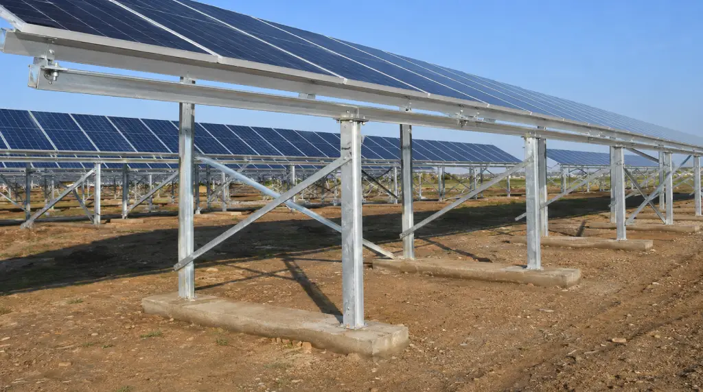
The exact terminology can differ between engineering drawings, but a typical fixed ground-mounted solar module mounting structure may include the following elements.
1. Foundation or Pile System
The foundation provides the interface between the mounting structure and the ground.
The appropriate foundation solution depends on the geotechnical conditions, structural loads and engineering design. Depending on the project, the design may use driven piles, concrete foundations, ground screws or another engineered solution.
Foundation selection should not be made independently of the structural design because the loads from the columns ultimately need to be transferred safely into the ground.
2. Columns or Posts
Columns are the primary vertical members of the structure. They connect the upper structural framework to the foundation or pile system.
The required section, length, steel thickness and connection configuration depend on the structural calculations and project drawings.
3. Rafters
Rafters form part of the main supporting frame and generally connect with the columns. They establish the structural geometry required to support the purlins and module rows.
The rafter arrangement can influence module inclination, member spacing and connection positions, so accurate dimensions and hole patterns are important during fabrication.
4. Purlins
Purlins provide the supporting lines closer to the photovoltaic modules. Depending on the approved structural design, solar projects may use C sections, HAT sections, Z sections or other cold-formed profiles.
Shree Deepak Industries manufactures galvanized C and Z purlins in multiple thicknesses and project-specific dimensions. For a solar project, the final profile and thickness should be selected according to the approved structural requirement.
5. Bracing Members
Bracing connects different structural members and contributes to the stability of the overall frame.
Its location, profile and connection details vary with the structural system, so bracing should be manufactured according to the approved drawing rather than treated as a standard accessory.
6. Connection Components and Fasteners
Bolts, nuts, washers, brackets, plates, clamps and other connection components bring the structural system together.
Connection geometry is especially important in large solar projects because the same detail may be repeated across hundreds or thousands of locations. Incorrect hole spacing or mismatched components can create significant installation difficulties at site.
Materials Commonly Used in Ground Mounted Solar Structures
There is no single material that is suitable for every ground-mounted solar project. Material selection depends on structural requirements, exposure conditions, corrosion protection, project specifications and the type of member being manufactured.
Galvanized Steel
Galvanized steel is widely used for outdoor structural applications because the zinc coating helps protect the underlying steel from direct environmental exposure.
The required steel grade, thickness and coating specification should be defined by the project documents. Different galvanized materials can have different mechanical and coating properties, so the term “GI” alone may not be enough for procurement purposes.
Galvalume or Aluminium-Zinc Coated Steel
Some solar mounting designs specify aluminium-zinc coated steel for selected members. As with galvanized steel, the exact material specification and coating requirement should correspond with the approved design.
Shree Deepak Industries lists galvanized, Galvalume and coated steel coils within its industrial steel product range.
Other Materials
Depending on the project and component, aluminium, stainless steel or other approved materials may also be used within solar mounting systems.
The decision should be based on engineering requirements and environmental exposure rather than selecting material only by initial price.
Key Design Considerations for a Ground Mounted Solar Structure
Ground-mounted solar structure design involves more than selecting a profile and specifying its thickness. Several project variables need to be considered together.
1. Structural Loads
The structure must be designed for the loads that can act on it during its intended use.
These may include the self-weight of the structure and modules, wind effects and other loads relevant to the project location and applicable design requirements.
Wind deserves particular attention because solar modules create large exposed surfaces. The resulting forces are transferred through purlins, rafters, columns, connections and finally into the foundations.
For this reason, a structural member should not be reduced or substituted simply because another profile appears visually similar.
2. Soil and Geotechnical Conditions
A ground-mounted system ultimately depends on the ground supporting it.
Soil type, bearing conditions, groundwater, rock, fill material and other site-specific geotechnical factors can influence foundation selection and installation methodology.
The same foundation approach may not be appropriate for every site. Ground information should therefore be considered during engineering rather than after the structural members have already been finalized.
3. Terrain and Site Levels
Real project sites are rarely perfectly flat.
Changes in ground level can affect pile exposure, column lengths, table geometry and installation tolerances. Large variations may require project-specific adjustments rather than forcing every table into an identical configuration.
Accurate survey information helps designers coordinate the structure with actual site conditions.
4. Module Tilt and Orientation
The mounting structure determines how modules are physically positioned.
Tilt angle and orientation affect the geometry of rafters, columns, purlins and connections. These parameters are usually established during plant design and should be reflected accurately in the structural drawings released for production.
A manufacturer should not independently alter the tilt or geometry simply to simplify fabrication.
5. Row Spacing and Shading
The distance between solar rows is part of the overall plant layout.
Row spacing needs to support the intended module arrangement while considering shading, access and project land utilization. Because structural dimensions interact with table geometry, changes in layout can also affect the mounting system.
6. Drainage and Water Movement
Ground-mounted solar projects cover large areas of land, so natural water movement and site drainage should not be overlooked.
Foundation locations, grading and access routes should be coordinated with the civil design so that the structure does not unintentionally interfere with drainage planning.
7. Section Geometry and Steel Thickness
A profile cannot be defined only as “C purlin” or “HAT purlin.”
Its structural behaviour depends on parameters such as:
- Web width
- Flange dimensions
- Lip dimensions where applicable
- Steel thickness
- Material grade
- Member length
- Hole and slot arrangement
Section selection should therefore follow the engineering drawings and calculations for the particular project.
8. Corrosion Protection and Environmental Exposure
Solar mounting structures remain outdoors for extended periods, making the required corrosion-protection system an important design and procurement consideration.
The appropriate coating depends on the project specification and exposure environment. Steel used in a dry inland site may face different conditions from material exposed to high humidity, industrial pollutants or other aggressive environments.
Buyers should define the required coating system clearly instead of relying on generic terms such as “galvanized structure.”
9. Connection Design and Punching Accuracy
Connections determine how loads move between the different structural members.
From a manufacturing perspective, this makes hole diameter, hole spacing, slot geometry and punching position critical parameters.
When the same connection is repeated across a large plant, even a small dimensional error can create repeated alignment problems during installation.
10. Manufacturing Tolerances
Ground-mounted projects often involve long production runs of similar profiles. Repeatability matters.
Profile dimensions, bend consistency, straightness, cut length and punching positions should remain within the tolerances agreed for the project.
Consistent manufacturing helps reduce unnecessary adjustments when components are assembled at site.
11. Installation Sequence and Constructability
A design can be structurally sound but still be unnecessarily difficult to install.
Constructability considerations include:
- How members will be handled at site
- Whether connection points are accessible
- How easily parts can be identified
- Whether module rows can be aligned efficiently
- How different profile lengths are bundled
- Whether the planned installation sequence matches the structural arrangement
Early coordination between engineering, manufacturing and site teams can reduce avoidable complications later.
12. Access for Inspection and Maintenance
The plant layout should also consider what happens after construction.
Reasonable access between rows can support inspection, vegetation management, cleaning, electrical maintenance and other operational activities. Structural geometry and site layout should therefore be viewed as part of the complete plant rather than in isolation.
Fixed-Tilt Structures vs Tracker Structures
Not every ground-mounted solar structure works in the same way.
Fixed-Tilt Structure
In a fixed-tilt system, the modules remain at a predetermined orientation after installation. The structural framework therefore uses a fixed geometry.
Its columns, rafters, purlins, bracing and foundations are engineered around that configuration.
Tracker Structure
A tracker system allows the module arrangement to move during operation. This introduces a different structural and mechanical system, including moving components and loads that are not present in a conventional fixed-tilt arrangement.
A fixed-tilt structure should therefore not be converted into a tracking configuration simply by changing a few members. The entire system requires project-specific engineering.
Why Slit Coil Quality Matters in Cold-Formed Solar Profiles
Many C, Z and HAT-type structural profiles begin as steel coil.
Before roll forming, the coil may be slit into narrower strips according to the developed width required for the final profile. Consistency in slit width and material thickness helps support repeatable profile forming.
Shree Deepak Industries lists GP, Zincalume and colour-coated slit coils for solar structures and other industrial applications.
For project-specific MMS production, the selected coil should match the approved steel grade, thickness and coating specification before forming begins.
What Should an EPC or Developer Confirm Before Ordering?
Before releasing a ground-mounted solar structure for manufacturing, the buyer and manufacturer should have a common understanding of the technical scope.
An RFQ or purchase package may include:
- Approved structural and fabrication drawings
- Bill of materials
- Section dimensions
- Steel grade
- Material thickness
- Coating specification
- Member lengths
- Punching and hole patterns
- Part identification requirements
- Inspection and documentation requirements
- Packaging and bundling requirements
- Quantity or project tonnage
- Delivery location
- Required dispatch schedule
Defining these requirements before production starts can reduce ambiguity during manufacturing and commercial comparison.
Common Mistakes to Avoid in Ground Mounted Solar Structures
Selecting Sections Only by Price
The lowest-cost section is not automatically the most suitable structural member. Material grade, thickness, geometry, coating and connection design all form part of the technical requirement.
Using Generic Profiles Without Checking the Approved Drawing
Two C sections may have completely different dimensions and structural properties. Ordering only by profile name can lead to incorrect material reaching the project.
Ignoring Soil Conditions Until Installation
Foundation design and the above-ground structure are connected. Unexpected ground conditions can affect installation, so geotechnical information should be considered early in the project.
Changing Material or Coating Without Engineering Review
Different grades and coating systems should not be treated as automatic substitutes. Any proposed deviation should be reviewed against the project requirement before implementation.
Underestimating Hole Alignment
Repeated connection errors can slow erection considerably. Hole geometry should be controlled with the same attention given to profile dimensions.
Poor Part Identification
Utility-scale installations may involve a large number of similar members. Clear bundle and part identification can make site reconciliation and installation substantially easier.
How Shree Deepak Industries Supports Solar Structure Requirements
Shree Deepak Industries is based in Jaipur, Rajasthan, and its website presents solar structure manufacturing capabilities around C, Z and HAT profile requirements, custom profile design, precision roll forming, coating protection, quality checks, packaging and dispatch planning.
The company’s existing product range also includes C and Z purlins, slit coils and steel coils relevant to structural and industrial applications.
Every ground-mounted solar project has its own engineering requirements. The final profile, steel grade, thickness, coating, punching pattern and dimensions should therefore be confirmed against the approved project drawings before manufacturing.
For a project-specific requirement, you can share your solar structure drawings, specifications, quantity and delivery location with Shree Deepak Industries for review and quotation.
Frequently Asked Questions About Ground Mounted Solar Structures
What is a ground mounted solar structure?
A ground mounted solar structure is the structural framework used to install photovoltaic modules on land rather than on a building roof. It transfers loads from the modules through the supporting members to the foundation or pile system.
What are the main components of a ground-mounted solar structure?
A typical fixed-tilt system may include foundations or piles, columns, rafters, purlins, bracing members, connection plates and fasteners. The exact configuration depends on the approved structural design.
Which material is commonly used for ground-mounted solar structures?
Projects may use galvanized steel, aluminium-zinc coated steel or other approved materials depending on structural and environmental requirements. There is no single material specification suitable for every site.
Are C purlins used in ground mounted solar structures?
Yes. C sections can be specified as purlins or other structural members depending on the MMS design. Their dimensions, steel grade and thickness should follow the engineering drawings.
Can HAT purlins be used in a ground-mounted solar project?
Yes, HAT sections can be used as module-supporting purlins when specified by the structural design. They should not automatically replace C or Z sections without engineering approval.
Why are soil conditions important for ground-mounted solar?
The structure transfers its loads into the ground through foundations or piles. Soil and geotechnical conditions therefore influence the type, size and installation method of the foundation system.
Why is wind important when designing solar mounting structures?
Solar modules create exposed surfaces on which wind can act. Those forces are transferred through the purlins, rafters, columns, connections and foundation system, making wind an important project-specific structural design input.
What information should be provided for a ground mounted solar structure quotation?
Where available, provide approved drawings, bill of materials, section sizes, steel grade, thickness, coating specification, hole patterns, quantities, inspection requirements and delivery location.
What is the difference between fixed-tilt and tracker structures?
A fixed-tilt system keeps the modules in a predetermined position, while a tracker system includes movement to change module orientation during operation. Their structural and mechanical requirements are therefore different.
Share thickness + size + quantity — we’ll reply with the best option.